Thursday, November 26, 2009

Magnetic Levitation


Levitating pyrolytic carbon.

Magnetic levitation, maglev, or magnetic suspension is a method by which an object is suspended with no support other than magnetic fields. Magnetic pressure is used to counteract the effects of the gravitational force.

Earnshaw's theorem proves that using only static ferromagnetism it is impossible to stably levitate against gravity, but servomechanisms, the use of diamagnetic materials, superconduction, or systems involving eddy currents permit this to occur.

In some cases the lifting force is provided by magnetic levitation, but there is a mechanical support bearing little load that provides stability. This is termed pseudo-levitation.

Magnetic levitation is used for maglev trains, magnetic bearings and for product display purposes.

Creative Commons: Wikipedia

Magnetic Bearing


A magnetic bearing is a bearing which supports a load using magnetic levitation. Magnetic bearings support moving machinery without physical contact, for example, they can levitate a rotating shaft and permit relative motion without friction or wear. They are in service in such industrial applications as electric power generation, petroleum refining, machine tool operation and natural gas pipelines. They are also used in the Zippe-type centrifuge used for uranium enrichment. Magnetic bearings are used in turbomolecular pumps where oil-lubricated bearings are a source of contamination. Magnetic bearings support the highest speeds of any kind of bearing; they have no known maximum relative speed.

Creative Commons: Wikipedia

Fluid Bearing


Fluid bearings are bearings which solely support the bearing's loads on a thin layer of liquid or gas.

They can be broadly classified as fluid dynamic bearings or hydrostatic bearings. Hydrostatic bearings are externally pressurized fluid bearings, where the fluid is usually oil, water or air, and the pressurization is done by a pump. Hydrodynamic bearings rely on the high speed of the journal self-pressurizing the fluid in a wedge between the faces.

Fluid bearings are frequently used in high load, high speed or high precision applications where ordinary ball bearings have short life or high noise and vibration. They are also used increasingly to reduce cost. For example, hard disk drive motor fluid bearings are both quieter and cheaper than the ball bearings they replace.

Creative Commons: Wikipedia

Bearing


A bearing is a device to allow constrained relative motion between two or more parts, typically rotation or linear movement. Bearings may be classified broadly according to the motions they allow and according to their principle of operation as well as by the directions of applied loads they can handle.

Bearing friction

Plain bearings are simply a hole of the correct shape containing the relatively moving part, and use surfaces in rubbing contact, often with a lubricant such as oil or graphite. They are very widely used. Particularly with lubrication they often give entirely acceptable life and friction.

However, reducing friction in bearings is often important for efficiency, to reduce wear and to facilitate extended use at high speeds and to avoid overheating and premature failure of the bearing. Essentially, a bearing can reduce friction by virtue of its shape, by its material, or by introducing and containing a fluid between surfaces or by separating the surfaces with an electromagnetic field.

By shape, gains advantage usually by using spheres or rollers, or by forming flexure bearings.
By material, exploits the nature of the bearing material used. (An example would be using plastics that have low surface friction.)

By fluid, exploits the low viscosity of a layer of fluid, such as a lubricant or as a pressurized medium to keep the two solid parts from touching, or by reducing the normal force between them.

By fields, exploits electromagnetic fields, such as magnetic fields, to keep solid parts from touching.

Combinations of these can even be employed within the same bearing. An example of this is where the cage is made of plastic, and it separates the rollers/balls, which reduce friction by their shape and finish.


An example of a four-point contact ball bearing.

Creative Commons: Wikipedia

Axle


Train wheels are affixed to a straight axle, such that both wheels rotate in unison. This is called a wheelset.

An axle is a central shaft for a rotating wheel or gear. In some cases the axle may be fixed in position with a bearing or bushing sitting inside the hole in the wheel or gear to allow the wheel or gear to rotate around the axle. In other cases the wheel or gear may be fixed to the axle, with bearings or bushings provided at the mounting points where the axle is supported. Sometimes, especially on bicycles, the latter type is referred to as a spindle.

Creative Commons: Wikipedia

Wedge


Wood Splitting Wedge

A wedge is a triangular shaped tool, a compound and portable inclined plane, and one of the six classical simple machines. It can be used to separate two objects or portions of an object, lift an object, or hold an object in place. It functions by converting a force applied to its blunt end into forces perpendicular (normal) to its inclined surfaces. The mechanical advantage of a wedge is given by the ratio of the length of its slope to its width. Although a short wedge with a wide angle may do a job faster, it requires more force than a long wedge with a narrow angle.


Cross-section of a splitting wedge with its length oriented vertically. A downward force produces forces perpendicular to its inclined surfaces.

Creative Commons : Wikipedia

Screw


A screw is one of the six simple machines. All screws are helical inclined planes. A screw can convert a rotational force (torque) to a linear force and vice versa. The ratio of threading determines the mechanical advantage of the machine. More threading increases the mechanical advantage. A rough comparison of mechanical advantage can be done by taking the circumference of the shaft of the screw and divide by the distance between the threads.

A screw is a shaft with a helical groove or thread formed on its surface and provision at one end to turn the screw. Its main uses are as a threaded fastener used to hold objects together, and as a simple machine used to translate torque into linear force. It can also be defined as an inclined plane wrapped around a shaft.

Screws come in a variety of shapes and sizes for different purposes.

Belt and Pulley Systems


A belt and pulley system is characterized by two or more pulleys in common to a belt. This allows for mechanical power, torque, and speed to be transmitted across axes and, if the pulleys are of differing diameters, a mechanical advantage to be realized.

A belt drive is analogous to that of a chain drive, however a belt sheave may be smooth (devoid of discrete interlocking members as would be found on a chain sprocket, spur gear, or timing belt) so that the mechanical advantage is approximately given by the ratio of the pitch diameter of the sheaves only, not fixed exactly by the ratio of teeth as with gears and sprockets.

In the case of a drum-style pulley, without a groove or flanges, the pulley often is slightly convex to keep the flat belt centered. Though once widely used in factory line shafts, this type of pulley is still found driving the rotating brush in upright vacuum cleaners.

Creative Commons: Wikipedia

Pulley


A pulley, also called a sheave or a drum, is a mechanism composed of a wheel on an axle or shaft that may have a groove between two flanges around its circumference. A rope, cable, belt, or chain usually runs over the wheel and inside the groove, if present. Pulleys are used to change the direction of an applied force, transmit rotational motion, or realize a mechanical advantage in either a linear or rotational system of motion. Two or more pulleys together are called a block and tackle.

Creative Commons: Wikipedia

Lever


Levers can be used to exert a large force over a small distance at one end by exerting only a small force over a greater distance at the other.

In physics, a lever (from French lever, "to raise", c.f. a levant) is a rigid object that is used with an appropriate fulcrum or pivot point to multiply the mechanical force that can be applied to another object. This leverage is also termed mechanical advantage, and is one example of the principle of moments. A lever is one of the six simple machines. Archimedes once said, "Give me a lever long enough and a fulcrum on which to place it, and I shall move the world." First class levers are similar but not the same as second or third class levers, in which the fulcrum, resistance, and effort are in different locations.

Creative Commons: Wikipedia

Machine


A machine is any device that uses energy to perform some activity. In common usage, the meaning is that of a device having parts that perform or assist in performing any type of work. A simple machine is a device that transforms the direction or magnitude of a force without consuming any energy. The word "machine" is derived from the Latin word machina.

Historically, a device required moving parts to be classified as a machine; however, the advent of electronics technology has led to the development of devices without moving parts that are considered machines—the computer being the most obvious example.

"Engines" are machines that convert heat or other forms of energy into mechanical energy. For example, in an internal combustion engine the expansion of gases caused by the heat from an exothermic chemical reaction results in a force being applied to a movable component, such as a piston or turbine blade.

Machines are ubiquitous in a wide variety of industrial, commercial, residential and transportation applications. Those employing hydraulics are especially useful in manufacturing and construction.

Creative Commons: Wikipedia

Oil Refinery


Crude oil is separated into fractions by fractional distillation. The fractions at the top of the fractionating column have lower boiling points than the fractions at the bottom. The heavy bottom fractions are often cracked into lighter, more useful products. All of the fractions are processed further in other refining units.

An oil refinery is an industrial process plant where crude oil is processed and refined into more useful petroleum products, such as gasoline, diesel fuel, asphalt base, heating oil, kerosene and liquefied petroleum gas. Oil refineries are typically large sprawling industrial complexes with extensive piping running throughout, carrying streams of fluids between large chemical processing units.

Operation

Raw or unprocessed crude oil is not generally useful. Although "light, sweet" (low viscosity, low sulfur) crude oil has been used directly as a burner fuel for steam vessel propulsion, the lighter elements form explosive vapors in the fuel tanks and are therefore hazardous, especially in warships. Instead, the hundreds of different hydrocarbon molecules in crude oil are separated in a refinery into components which can be used as fuels, lubricants, and as feedstock in petrochemical processes that manufacture such products as plastics, detergents, solvents, elastomers and fibers such as nylon and polyesters.

Petroleum fossil fuels are burned in internal combustion engines to provide power for ships, automobiles, aircraft engines, lawn mowers, chainsaws, and other machines. Different boiling points allow the hydrocarbons to be separated by distillation. Since the lighter liquid products are in great demand for use in internal combustion engines, a modern refinery will convert heavy hydrocarbons and lighter gaseous elements into these higher value products.

Oil can be used in a variety of ways because it contains hydrocarbons of varying molecular masses, forms and lengths such as paraffins, aromatics, naphthenes (or cycloalkanes), alkenes, dienes, and alkynes. While the molecules in crude oil include different atoms such as sulfur and nitrogen, the hydrocarbons are the most common form of molecules, which are molecules of varying lengths and complexity made of hydrogen and carbon atoms, and a small number of oxygen atoms. The differences in the structure of these molecules account for their varying physical and chemical properties, and it is this variety that makes crude oil useful in a broad range of applications.

Once separated and purified of any contaminants and impurities, the fuel or lubricant can be sold without further processing. Smaller molecules such as isobutane and propylene or butylenes can be recombined to meet specific octane requirements by processes such as alkylation, or less commonly, dimerization. Octane grade of gasoline can also be improved by catalytic reforming, which involves removing hydrogen from hydrocarbons producing compounds with higher octane ratings such as aromatics. Intermediate products such as gasoils can even be reprocessed to break a heavy, long-chained oil into a lighter short-chained one, by various forms of cracking such as fluid catalytic cracking, thermal cracking, and hydrocracking. The final step in gasoline production is the blending of fuels with different octane ratings, vapor pressures, and other properties to meet product specifications.

Oil refineries are large scale plants, processing about a hundred thousand to several hundred thousand barrels of crude oil a day. Because of the high capacity, many of the units operate continuously, as opposed to processing in batches, at steady state or nearly steady state for months to years. The high capacity also makes process optimization and advanced process control very desirable.


Creative Commons: Wikipedia

Tunnel Thrusters


Large vessels usually have one or more tunnels built into the bow below the waterline. An impeller in the tunnel can create thrust in either direction which makes the ship turn. Most tunnel thrusters are driven by electric motors, but some are hydraulically powered. These bow thrusters, also known as tunnel thrusters, may allow the ship to dock without the assistance of tugboats, saving the costs of such service. Ships equipped with tunnel thrusters typically have a sign above the waterline over each thruster on both sides, a big white cross in a white circle.

Tunnel thrusters increase the vessel's resistance to forward motion through the water, but this can be mitigated through proper fairing aft of the tunnel aperture (see below photo). Ship operators should take care to prevent fouling of the tunnel and impeller, either through use of a protective grate or by cleaning. During vessel design, it is important to determine whether tunnel emergence above the water surface is commonplace in heavy seas. Tunnel emergence hurts thruster performance, and may damage the thruster and the hull around it.

Rolls-Royce Merlin


The Rolls-Royce Merlin is a British, liquid-cooled, 27-litre (1,650 cu in) capacity, V-12 piston aero engine, designed and built by Rolls-Royce Limited. Initially known as the PV-12, Rolls-Royce named the engine the Merlin following the company convention of naming its piston aero engines after birds of prey.

The PV-12 first ran in 1933, and a series of rapidly applied developments brought about by wartime needs improved the engine's performance markedly. The first operational aircraft to enter service using the Merlin were the Fairey Battle, Hawker Hurricane and Supermarine Spitfire. More Merlins were made for the four-engined Avro Lancaster heavy bomber than any other aircraft; however, the engine is most closely associated with the Spitfire and powered its maiden flight in 1936.

An English icon, the Merlin was one of the most successful aircraft engines of the World War II era, and many variants were built by Rolls-Royce in Derby, Crewe and Glasgow, as well as by Ford of Britain in Trafford Park, Manchester. The Packard V-1650 was a version of the Merlin built in the United States. Production ceased in 1950 after a total of almost 150,000 engines had been delivered, the later variants being used for airliners and military transport aircraft.
In military use the Merlin was superseded by its larger capacity stablemate, the Rolls-Royce Griffon. Merlin engines remain in Royal Air Force service today with the Battle of Britain Memorial Flight, and power many restored aircraft in private ownership worldwide.

Analog Computers


A page from the Bombardier's Information File (BIF) that describes the components and controls of the Norden bombsight. The Norden bombsight was a highly sophisticated optical/mechanical analog computer used by the United States Army Air Force during World War II, the Korean War, and the Vietnam War to aid the pilot of a bomber aircraft in dropping bombs accurately.

An analog computer (spelled analogue in British English) is a form of computer that uses the continuously-changeable aspects of physical phenomena such as electrical, mechanical, or hydraulic quantities to model the problem being solved. In contrast, digital computers represent varying quantities incrementally, as their numerical values change.

Mechanical analog computers were very important in gun fire control in World War II and the Korean War; they were made in significant numbers. In particular, development of transistors made electronic analog computers practical, and before digital computers had developed sufficiently, they were commonly used in science and industry.

Analog computers can have a very wide range of complexity. Slide rules and nomographs are the simplest, while naval gun fire control computers and large hybrid digital/analogue computers were among the most complicated. Digital computers have a certain minimum (and relatively great) degree of complexity that is far greater than that of the simpler analog computers. This complexity is required to execute their stored programs, and in many instances for creating output that is directly suited to human use.

Setting up an analog computer required scale factors to be chosen, along with initial conditions – that is, starting values. Another essential was creating the required network of interconnections between computing elements. Sometimes it was necessary to re-think the structure of the problem so that the computer would function satisfactorily. No variables could be allowed to exceed the computer's limits, and differentiation was to be avoided, typically by rearranging the "network" of interconnects, using integrators in a different sense.

Running an electronic analog computer, assuming a satisfactory setup, started with the computer held with some variables fixed at their initial values. Moving a switch released the holds and permitted the problem to run. In some instances, the computer could, after a certain running time interval, repeatedly return to the initial-conditions state to reset the problem, and run it again.

Creative Commons: Wikipedia

Electronic


Electronics is a branch of science and technology that deals with the controlled flow of electrons. The ability to control electron flow is usually applied to information handling or device control. Electronics is distinct from electrical science and technology, which deals with the generation, distribution, control and application of electrical power. This distinction started around 1906 with the invention by Lee De Forest of the triode, which made electrical amplification possible with a non-mechanical device. Until 1950 this field was called "radio technology" because its principal application was the design and theory of radio transmitters, receivers and vacuum tubes.

Most electronic devices today use semiconductor components to perform electron control. The study of semiconductor devices and related technology is considered a branch of physics, whereas the design and construction of electronic circuits to solve practical problems come under electronics engineering. This article focuses on engineering aspects of electronics.

Hydraulic Machine


Hydraulic machinery are machines and tools which use fluid power to do work. Heavy equipment is a common example.

In this type of machine, high-pressure liquid — called hydraulic fluid — is transmitted throughout the machine to various hydraulic motors and hydraulic cylinders. The fluid is controlled directly or automatically by control valves and distributed through hoses and tubes.
The popularity of hydraulic machinery is due to the very large amount of power that can be transferred through small tubes and flexible hoses, and the high power density and wide array of actuators that can make use of this power.

Hydraulic machinery is operated by the use of hydraulics, where a liquid is the powering medium. Pneumatics, on the other side, is based on the use of a gas as the medium for power transmission, generation and control.

Electric Motor


An electric motor is a motor that uses electrical energy to produce mechanical energy, usually through the interaction of magnetic fields and current-carrying conductors. The reverse process, producing electrical energy from mechanical energy, is accomplished by a generator or dynamo. Traction motors used on vehicles often perform both tasks. Electric motors can be run as generators and vice versa, although this is not always practical. Electric motors are ubiquitous, being found in applications as diverse as industrial fans, blowers and pumps, machine tools, household appliances, power tools, and disk drives. They may be powered by direct current (for example a battery powered portable device or motor vehicle), or by alternating current from a central electrical distribution grid. The smallest motors may be found in electric wristwatches. Medium-size motors of highly standardized dimensions and characteristics provide convenient mechanical power for industrial uses. The very largest electric motors are used for propulsion of large ships, and for such purposes as pipeline compressors, with ratings in the millions of watts. Electric motors may be classified by the source of electric power, by their internal construction, and by their application.

The physical principle of production of mechanical force by the interactions of an electric current and a magnetic field was known as early as 1821. Electric motors of increasing efficiency were constructed throughout the 19th century, but commercial exploitation of electric motors on a large scale required efficient electrical generators and electrical distribution networks.

By convention, electric engine refers to a railroad electric locomotive, rather than an electric motor.

Wednesday, November 25, 2009

Manufacturing


Manufacturing is the use of machines, tools and labor to make things for use or sale. The term may refer to a range of human activity, from handicraft to high tech, but is most commonly applied to industrial production, in which raw materials are transformed into finished goods on a large scale. Such finished goods may be used for manufacturing other, more complex products, such as household appliances or automobiles, or sold to wholesalers, who in turn sell them to retailers, who then sell them to end users - the "consumers".

Manufacturing takes turns under all types of economic systems. In a free market economy, manufacturing is usually directed toward the mass production of products for sale to consumers at a profit. In a collectivist economy, manufacturing is more frequently directed by the state to supply a centrally planned economy. In free market economies, manufacturing occurs under some degree of government regulation.

Modern manufacturing includes all intermediate processes required for the production and integration of a product's components. Some industries, such as semiconductor and steel manufacturers use the term fabrication instead.

The manufacturing sector is closely connected with engineering and industrial design. Examples of major manufacturers in the United States include General Motors Corporation, Ford Motor Company, Chrysler, Boeing, Gates Corporation and Pfizer. Examples in Europe include Airbus, Daimler, BMW, Fiat, and Michelin Tyre.

Source: Wikipedia

Tuesday, November 24, 2009

Automobile


An automobile, motor car or car is a wheeled motor vehicle used for transporting passengers, which also carries its own engine or motor. Most definitions of the term specify that automobiles are designed to run primarily on roads, to have seating for one to eight people, to typically have four wheels, and to be constructed principally for the transport of people rather than goods. However, the term automobile is far from precise, because there are many types of vehicles that do similar tasks.

As of 2002, there were 590 million passenger cars worldwide (roughly one car per eleven people). Around the world, there were about 806 million cars and light trucks on the road in 2007; they burn over 260 billion gallons of gasoline and diesel fuel yearly. The numbers are increasing rapidly, especially in China and India.

Source: Wikipedia

Wright Brothers


The Wright brothers, Orville (August 19, 1871 – January 30, 1948) and Wilbur (April 16, 1867 – May 30, 1912), were two Americans who are generally credited with inventing and building the world's first successful airplane and making the first controlled, powered and sustained heavier-than-air human flight, on December 17, 1903. They are also officially credited worldwide through the Fédération Aéronautique Internationale, the standard-setting and record-keeping body for aeronautics and astronautics, as "the first sustained and controlled heavier-than-air powered flight." In the two years afterward, the brothers developed their flying machine into the first practical fixed-wing aircraft. Although not the first to build and fly experimental aircraft, the Wright brothers were the first to invent aircraft controls that made fixed-wing flight possible.

The brothers' fundamental breakthrough was their invention of three-axis control, which enabled the pilot to steer the aircraft effectively and to maintain its equilibrium. This method became standard and remains standard on fixed-wing aircraft of all kinds. From the beginning of their aeronautical work, the Wright brothers focused on unlocking the secrets of control to conquer "the flying problem," rather than developing more powerful engines as some other experimenters did. Their careful wind tunnel tests produced better aeronautical data than any before, enabling them to design and build wings and propellers more effective than any before. Their U.S. patent 821,393 claims the invention of a system of aerodynamic control that manipulates a flying machine's surfaces.

They gained the mechanical skills essential for their success by working for years in their shop with printing presses, bicycles, motors, and other machinery. Their work with bicycles in particular influenced their belief that an unstable vehicle like a flying machine could be controlled and balanced with practice. From 1900 until their first powered flights in late 1903, they conducted extensive glider tests that also developed their skills as pilots. Their bicycle shop employee Charlie Taylor became an important part of the team, building their first aircraft engine in close collaboration with the brothers.

The Wright brothers' status as inventors of the airplane has been subject to counter-claims by various parties. Much controversy persists over the many competing claims of early aviators.


Source: Wikipedia

Monday, November 23, 2009

Ramjet - Aircraft Engine System


A ramjet, sometimes referred to as a stovepipe jet, or an athodyd, is a form of jet engine using the engine's forward motion to compress incoming air, without a rotary compressor. Ramjets cannot produce thrust at zero airspeed and thus cannot move an aircraft from a standstill.

Ramjets require considerable forward speed to operate well, and as a class work most efficiently at speeds around Mach 3. This type of jet can operate up to speeds of at least Mach 5.
Ramjets can be particularly useful in applications requiring a small and simple engine for high speed use; such as missiles, while weapon designers are looking to use ramjet technology in artillery shells to give added range; it is anticipated that a 120-mm mortar shell, if assisted by a ramjet, could attain a range of 22 mi (35 km). They have also been used successfully, though not efficiently, as tip jets on helicopter rotors.

Ramjets are frequently confused with pulsejets, which use an intermittent combustion, but ramjets employ a continuous combustion process, and are a quite distinct type of jet engine.

Sunday, November 22, 2009

The History of Helicopters

The earliest references for vertical flight have come from China. Since 400 BC, Chinese children have played with bamboo flying toys and a book written in 4th-century China, referred to as Pao Phu Tau (also Pao Phu Tzu or Bao Pu Zi, 抱朴子), is reported to describe some of the ideas inherent to rotary wing aircraft:

“Someone asked the master about the principles of mounting to dangerous heights and traveling into the vast inane. The Master said, "Some have made flying cars with wood from the inner part of the jujube tree, using ox-leather [straps] fastened to returning blades so as to set the machine in motion.”


da Vinci's "aerial screw"

It was not until the early 1480s, when Leonardo da Vinci created a design for a machine that could be described as an "aerial screw", that any recorded advancement was made towards vertical flight. His notes suggested that he built small flying models, but there were no indications for any provision to stop the rotor from making the whole craft rotate. As scientific knowledge increased and became more accepted, men continued to pursue the idea of vertical flight. Many of these later models and machines would more closely resemble the ancient bamboo flying top with spinning wings, rather than Da Vinci's screw.

In July 1754, Mikhail Lomonosov demonstrated a small coaxial rotor to the Russian Academy of Sciences. It was powered by a spring and suggested as a method to lift meteorological instruments. In 1783, Christian de Launoy, and his mechanic, Bienvenu, made a model with a pair of counter-rotating rotors, using turkey's flight feathers as rotor blades, and in 1784, demonstrated it to the French Academy of Sciences. Sir George Cayley, influenced by a childhood fascination with the Chinese flying top, grew up to develop a model of feathers, similar to Launoy and Bienvenu, but powered by rubber bands. By the end of the century, he had progressed to using sheets of tin for rotor blades and springs for power. His writings on his experiments and models would become influential on future aviation pioneers. Alphonse Pénaud would later develop coaxial rotor model helicopter toys in 1870, also powered by rubber bands. One of these toys, given as a gift by their father, would inspire the Wright brothers to pursue the dream of flight.

In 1861, the word "helicopter" was coined by Gustave de Ponton d'Amécourt, a French inventor who demonstrated a small, steam-powered model. While celebrated as an innovative use of a new metal, aluminum, the model never lifted off the ground. D'Amecourt's linguistic contribution would survive to eventually describe the vertical flight he had envisioned. Steam power was popular with other inventors as well. Enrico Forlanini's unmanned helicopter was also powered by a steam engine. It was the first of its type that rose to a height of 13 meters (43 ft), where it remained for some 20 seconds after a vertical take-off from a park in Milan, in 1877. Emmanuel Dieuaide's steam-powered design featured counter-rotating rotors powered through a hose from a boiler on the ground. Dandrieux's design had counter-rotating rotors and a 7.7-pound (3.5-kilogram) steam engine. It rose more than 40 feet (12 m) and flew for 20 seconds circa 1878.

In 1885, Thomas Edison was given US$1,000 by James Gordon Bennett, Jr., to conduct experiments towards developing flight. Edison built a helicopter and used the paper for a stock ticker to create guncotton, with which he attempted to power an internal combustion engine. The helicopter was damaged by explosions and one of his workers was badly burned. Edison reported that it would take a motor with a ratio of three to four pounds per horsepower produced to be successful, based on his experiments. Ján Bahýľ, a Slovak inventor, adapted the internal combustion engine to power his helicopter model that reached a height of 0.5 meters (1.6 ft) in 1901. On 5 May 1905, his helicopter reached four meters (13 ft) in altitude and flew for over 1,500 meters (4,900 ft). In 1908, Edison patented his own design for a helicopter powered by a gasoline engine with box kites attached to a mast by cables for a rotor, but it never flew.

First Flights

In 1906, two French brothers, Jacques and Louis Breguet, began experimenting with airfoils for helicopters and in 1907, those experiments resulted in the Gyroplane No.1. Although there is some uncertainty about the dates, sometime between 14 August and 29 September 1907, the Gyroplane No. 1 lifted its pilot up into the air about two feet (0.6 m) for a minute. However, the Gyroplane No. 1 proved to be extremely unsteady and required a man at each corner of the airframe to hold it steady. For this reason, the flights of the Gyroplane No. 1 are considered to be the first manned flight of a helicopter, but not a free or untethered flight.


Paul Cornu's helicopter in 1907

That same year, fellow French inventor Paul Cornu designed and built a Cornu helicopter that used two 20-foot (6 m) counter-rotating rotors driven by a 24-hp (18-kW) Antoinette engine. On 13 November 1907, it lifted its inventor to 1 foot (0.3 m) and remained aloft for 20 seconds. Even though this flight did not surpass the flight of the Gyroplane No. 1, it was reported to be the first truly free flight with a pilot.[n 1] Cornu's helicopter would complete a few more flights and achieve a height of nearly 6.5 feet (2 m), but it proved to be unstable and was abandoned.

Early Development

In the early 1920s, Argentine Raúl Pateras Pescara, while working in Europe, demonstrated one of the first successful applications of cyclic pitch.[3] Coaxial, contra-rotating, biplane rotors could be warped to cyclically increase and decrease the lift they produced. The rotor hub could also be tilted forward a few degrees, allowing the aircraft to move forward without a separate propeller to push or pull it. Pescara was also able to demonstrate the principle of autorotation, by which helicopters safely land after engine failure. By January 1924, Pescara's helicopter No. 3 could fly for up ten minutes.


Oehmichen N°2 1922

One of Pescara's contemporaries, Frenchman Etienne Oehmichen, set the first helicopter world record recognized by the Fédération Aéronautique Internationale (FAI) on 14 April 1924, flying his helicopter 360 meters (1,181 ft). On 18 April 1924, Pescara beat Oemichen's record, flying for a distance of 736 meters (nearly a half mile) in 4 minutes and 11 seconds (about 8 mph, 13 km/h) maintaining a height of six feet (2 m).[16] Not to be outdone, Oehmichen reclaimed the world record on 4 May when he flew his No. 2 machine again for a 14-minute flight covering 5,550 feet (1.05 mi, 1.69 km) while climbing to a height of 50 feet (15 m). Oehmichen also set the 1 km closed-circuit record at 7 minutes 40 seconds.

Meanwhile, Juan de la Cierva was developing the first practical rotorcraft in Spain. In 1923, the aircraft that would become the basis for the modern helicopter rotor began to take shape in the form of an autogyro, Cierva's C.4. Cierva had discovered aerodynamic and structural deficiencies in his early designs that could cause his autogyros to flip over after takeoff. The flapping hinges that Cierva designed for the C.4 allowed the rotor to develop lift equally on the left and right halves of the rotor disk. A crash in 1927, led to the development of a drag hinge to relieve further stress on the rotor from its flapping motion.[17] These two developments allowed for a stable rotor system, not only in a hover, but in forward flight.
Albert Gillis von Baumhauer, a Dutch aeronautical engineer, began studying rotorcraft design in 1923. His first prototype "flew" ("hopped" and hovered in reality) on 24 September 1925, with Dutch Army-Air arm Captain Floris Albert van Heijst at the controls. The controls that Captain van Heijst used were Von Baumhauer's inventions, the cyclic and collective. Patents were granted to von Baumhauer for his cyclic and collective controls by the British ministry of aviation on 31 January 1927, under patent number 265,272.

In 1930, the Italian engineer Corradino D'Ascanio built his D'AT3, a coaxial helicopter. His relatively large machine had two, two-bladed, counter-rotating rotors. Control was achieved by using auxiliary wings or servo-tabs on the trailing edges of the blades,[18] a concept that was later adopted by other helicopter designers, including Bleeker and Kaman. Three small propellers mounted to the airframe were used for additional pitch, roll, and yaw control. The D'AT3 held modest FAI speed and altitude records for the time, including altitude (18 m or 59 ft), duration (8 minutes 45 seconds) and distance flown (1,078 m or 3,540 ft).

At this same time, in the Soviet Union, the aeronautical engineers Boris N. Yuriev and Alexei M. Cheremukhin, working at TsAGI, constructed and flew the TsAGI 1-EA single rotor helicopter, which used an open tubing framework, a four blade main rotor, and twin sets (one set of two each at the nose and tail) of 1.8 meters (6 ft) diameter anti-torque rotors. Powered by two M-2 powerplants, themselves up-rated Soviet copies of the Gnome Monosoupape rotary radial engine of World War I, the TsAGI 1-EA made several successful low altitude flights, and by 14 August 1932 Cheremukhin managed to get the 1-EA up to an unofficial altitude of 605 meters (1,985 ft), shattering d'Ascanio's earlier achievement. As the Soviet Union was not yet a member of the FAI, however, Cheremukhin's record remained unrecognized.

Nicolas Florine, a Russian engineer, built the first twin tandem rotor machine to perform a free flight. It flew in Sint-Genesius-Rode, at the Laboratoire Aérotechnique de Belgique (now von Karman Institute) in April 1933, and attained an altitude of six meters (20 ft) and an endurance of eight minutes. Florine chose a co-rotating configuration because the gyroscopic stability of the rotors would not cancel. Therefore the rotors had to be tilted slightly in opposite directions to counter torque. Using hingeless rotors and co-rotation also minimised the stress on the hull. At the time, it was probably the most stable helicopter in existence.
The Bréguet-Dorand Gyroplane Laboratoire was built in 1933. After many ground tests and an accident, it first took flight on 26 June 1935. Within a short time, the aircraft was setting records with pilot Maurice Claisse at the controls. On 14 December 1935, he set a record for closed-circuit flight with a 500-meter (1,600 ft) diameter. The next year, on 26 September 1936, Claisse set a height record of 158 meters (520 ft). And, finally, on 24 November 1936, he set a flight duration record of one hour, two minutes and 5 seconds over a 44 kilometer (27 mi) closed circuit at 44.7 kilometers per hour (27.8 mph). The aircraft was destroyed in 1943 by an Allied airstrike at Villacoublay airport.

Birth of an industry


First airmail service by helicopter in Los Angeles, 1947.

Despite the success of the Gyroplane Laboratoire, the German Focke-Wulf Fw 61, first flown in 1936, would eclipse its accomplishments. The Fw 61 broke all of the helicopter world records in 1937, demonstrating a flight envelope that had only previously been achieved by the autogyro. In February 1938, Hanna Reitsch became the first female helicopter pilot, exhibiting the Fw 61 before crowds in the Deutschlandhalle.

Nazi Germany would use helicopters in small numbers during World War II for observation, transport, and medical evacuation. The Flettner Fl 282 Kolibri synchropter was used in the Mediterranean Sea, while the Focke Achgelis Fa 223 Drache was used in Europe. Extensive bombing by the Allied forces prevented Germany from producing any helicopters in large quantities during the war.

In the United States, Igor Sikorsky and W. Lawrence LePage, were competing to produce the United States military's first helicopter. Prior to the war, LePage had received the patent rights to develop helicopters patterned after the Fw 61, and built the XR-1. Meanwhile, Sikorsky had settled on a simpler, single rotor design, the VS-300. After experimenting with configurations to counteract the torque produced by the single main rotor, he settled on a single, smaller rotor mounted vertically on the tailboom.

Developed from the VS-300, Sikorsky's R-4 became the first mass produced helicopter with a production order for 100 aircraft. The R-4 was the only Allied helicopter to see service in World War II, primarily being used for rescue in Burma, Alaska, and other areas with harsh terrain. Total production would reach 131 helicopters before the R-4 was replaced by other Sikorsky helicopters such as the R-5 and the R-6. In all, Sikorsky would produce over 400 helicopters before the end of World War II.

As LePage and Sikorsky were building their helicopters for the military, Bell Aircraft hired Arthur Young to help build a helicopter using Young's semi-rigid, teetering-blade rotor design, which used a weighted stabilizing bar. The subsequent Model 30 helicopter demonstrated the simplicity and ease of the design. The Model 30 was developed into the Bell 47, which became the first helicopter certificated for civilian use in the United States. Produced in several countries, the Bell 47 would become the most popular helicopter model for nearly 30 years.

Turbine age

In 1951, at the urging of his contacts at the Department of the Navy, Charles Kaman modified his K-225 helicopter with a new kind of engine, the turboshaft engine. This adaptation of the turbine engine provided a large amount of power to the helicopter with a lower weight penalty than piston engines, with their heavy engine blocks and auxiliary components. On 11 December 1951, the Kaman K-225 became the first turbine-powered helicopter in the world. Two years later, on 26 March 1954, a modified Navy HTK-1, another Kaman helicopter, became the first twin-turbine helicopter to fly. However, it was the Sud Aviation Alouette II that would become the first helicopter to be produced with a turbine-engine.

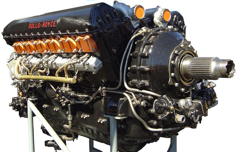
Reliable helicopters capable of stable hover flight were developed decades after fixed-wing aircraft. This is largely due to higher engine power density requirements than fixed-wing aircraft. Improvements in fuels and engines during the first half of the 20th century were a critical factor in helicopter development. The availability of lightweight turboshaft engines in the second half of the 20th century led to the development of larger, faster, and higher-performance helicopters. While smaller and less expensive helicopters still use piston engines, turboshaft engines are the preferred powerplant for helicopters today.

Source: Wikipedia

Helicopter


A helicopter is a type of rotorcraft in which lift and thrust are supplied by one or more engine driven rotors. In contrast with fixed-wing aircraft, this allows the helicopter to take off and land vertically, to hover, and to fly forwards, backwards and laterally. These attributes allow helicopters to be used in congested or isolated areas where fixed-wing aircraft would not be able to take off or land. The capability to hover for extended periods of time, and more efficiently than other forms of vertical takeoff and landing aircraft, allows helicopters to accomplish tasks that fixed-wing aircraft cannot perform.

The word 'helicopter' is adapted from the French hélicoptère, coined by Gustave de Ponton d'Amecourt in 1861, which originates from the Greek helix/helik- (ἕλικ-) = 'spiral' or 'turning' and pteron (πτερόν) = 'wing'.

Helicopters were developed and built during the first half-century of flight, with some reaching limited production, but it was not until 1942 that a helicopter designed by Igor Sikorsky reached full-scale production, with 131 aircraft built. Though most earlier designs used more than one main rotor, it was the single main rotor with antitorque tail rotor configuration of this design that would come to be recognized worldwide as the helicopter.

Source: Wikipedia.

Friday, November 20, 2009

Solar System


The Solar System[a] consists of the Sun and those celestial objects bound to it by gravity, all of which formed from the collapse of a giant molecular cloud approximately 4.6 billion years ago. Of the retinue of objects that orbit the Sun, most of the mass is contained within eight relatively solitary planets whose orbits are almost circular and contained within a nearly-flat disc called the ecliptic plane. The four smaller inner planets; Mercury, Venus, Earth and Mars, also called the terrestrial planets, are primarily composed of rock and metal. The four outer planets, Jupiter, Saturn, Uranus and Neptune, also called the gas giants, are composed largely of hydrogen and helium and are far more massive than the terrestrials.

The Solar System is also home to two regions populated by smaller objects. The asteroid belt, which lies between Mars and Jupiter, is similar to the terrestrial planets as it is composed mainly of rock and metal. Beyond Neptune's orbit lie trans-Neptunian objects composed mostly of ices such as water, ammonia and methane. Within these regions, five individual objects, Ceres, Pluto, Haumea, Makemake and Eris, are recognised to be large enough to have been rounded by their own gravity, and are thus termed dwarf planets. In addition to thousands of small bodies in those two regions, various other small body populations, such as comets, centaurs and interplanetary dust, freely travel between regions.

The solar wind, a flow of plasma from the Sun, creates a bubble in the interstellar medium known as the heliosphere, which extends out to the edge of the scattered disc. The hypothetical Oort cloud, which acts as the source for long-period comets, may also exist at a distance roughly a thousand times further than the heliosphere.

Six of the planets and three of the dwarf planets are orbited by natural satellites,[b] usually termed "moons" after Earth's Moon. Each of the outer planets is encircled by planetary rings of dust and other particles.

Source: Wikipedia

Fly-by-wire Control Systems


An Airbus A321 aircraft fly by wire cockpit.

Mechanical and hydro-mechanical flight control systems are heavy and require careful routing of flight control cables through the aircraft using systems of pulleys, cranks, wires and with hydraulically-assisted controls, hydraulic pipes. Both systems often require redundant backup to deal with failures, which again increases weight. Furthermore, both have limited ability to compensate for changing aerodynamic conditions. Dangerous characteristics such as stalling, spinning and pilot-induced oscillation (PIO), which depend mainly on the stability and structure of the aircraft concerned rather than the control system itself, can still occur with these systems.

A fly-by-wire system actually replaces manual control of the aircraft with an electronic interface. The movements of flight controls are converted to electronic signals, and flight control computers determine how to move the actuators at each control surface to provide the expected response. The actuators are usually hydraulic, but electric actuators have also been used.

By using electrical control circuits combined with computers, designers can save weight, improve reliability, and use the computers to mitigate the undesirable characteristics mentioned above. Advanced modern fly-by-wire systems are also used to control otherwise unstable fighter aircraft.

The words "Fly-by-Wire" (FBW) imply an electrically-signaled only control system. However, the term is generally used in the sense of computer-configured controls, where a computer system is interposed between the operator and the final control actuators or surfaces. This modifies the manual inputs of the pilot in accordance with control parameters. These are carefully developed and validated in order to produce maximum operational effect without compromising safety.
Safety and Redundancy

Aircraft systems may be quadruplexed (four independent channels) in order to prevent loss of signals in the case of failure of one or even two channels. High performance aircraft that have FBW controls (also called CCVs or Control-Configured Vehicles) may be deliberately designed to have low or even negative aerodynamic stability in some flight regimes, the rapid-reacting CCV controls compensating for the lack of natural stability.

Weight Saving

A FBW aircraft can be lighter than a similar design with conventional controls. Partly due to the lower overall weight of the system components; and partly because the natural aerodynamic stability of the aircraft can be relaxed, slightly for a transport aircraft and more for a maneuverable fighter, which means that the stability surfaces that are part of the aircraft structure can therefore be made smaller. These include the vertical and horizontal stabilizers (fin and tailplane) that are (normally) at the rear of the fuselage. If these structures can be reduced in size, airframe weight is reduced. The advantages of FBW controls were first exploited by the military and then in the commercial airline market. The Airbus series of airliners used full-authority FBW controls beginning with their A320 series, see A320 flight control (though some limited FBW functions existed on A310). Boeing followed with their 777 and later designs.
Electronic fly-by-wire systems can respond flexibly to changing aerodynamic conditions, by tailoring flight control surface movements so that aircraft response to control inputs is appropriate to flight conditions. Electronic systems require less maintenance, whereas mechanical and hydraulic systems require lubrication, tension adjustments, leak checks, fluid changes, etc. Furthermore, putting circuitry between pilot and aircraft can enhance safety; for example the control system can try to prevent a stall, or it can stop the pilot from over stressing the airframe.

The main concern with fly-by-wire systems is reliability. While traditional mechanical or hydraulic control systems usually fail gradually, the loss of all flight control computers could immediately render the aircraft uncontrollable. For this reason, most fly-by-wire systems incorporate either redundant computers (triplex, quadruplex etc), some kind of mechanical or hydraulic backup or a combination of both. A "mixed" control system such as the latter is not desirable and modern FBW aircraft normally avoid it by having more independent FBW channels, thereby reducing the possibility of overall failure to minuscule levels that are acceptable to the independent regulatory and safety authority responsible for aircraft design, testing and certification before operational service.

Analog

The fly-by-wire flight control system eliminates the complexity, fragility and weight of the mechanical circuit of the hydromechanical flight control systems and replaces it with an electrical circuit. The cockpit controls now operate signal transducers which generate the appropriate commands, that are in turn processed by an electronic controller. The autopilot is now part of the electronic controller.

The hydraulic circuits are similar except that mechanical servo valves are replaced with electrically-controlled servo valves, operated by the electronic controller. This is the simplest and earliest configuration of an analog fly-by-wire flight control system, as first fitted to the Avro Vulcan in the 1950s.

In this configuration, the flight control systems must simulate "feel". The electronic controller controls electrical feel devices that provide the appropriate "feel" forces on the manual controls. This is still used in the Embraer E-Jets family of aircraft and was used in Concorde, the first fly-by-wire airliner.

In more sophisticated versions, analog computers replaced the electronic controller. The cancelled 1950s supersonic Canadian fighter, the Avro CF-105 Arrow, employed this type of system. Analog computers also allowed some customization of flight control characteristics, including relaxed stability. This was exploited by the early versions of F-16, giving it impressive maneuverability.

Digital


F-8C Crusader digital fly-by-wire testbed


The Airbus A320, first airliner with digital fly-by-wire controls.


A Dassault Falcon 7X, the first business jet with digital fly-by-wire controls.

A digital fly-by-wire flight control system is similar to its analog counterpart. However, the signal processing is done by digital computers and the pilot literally can "fly-via-computer". This increases flexibility as the digital computers can receive input from any aircraft sensor. It also increases electronic stability, because the system is less dependent on the values of critical electrical components in an analog controller.

The computers "read" position and force inputs from the pilot's controls and aircraft sensors. They solve differential equations to determine the appropriate command signals that move the flight controls in order to carry out the intentions of the pilot.

The programming of the digital computers enable flight envelope protection. In this aircraft designers precisely tailor an aircraft's handling characteristics, to stay within the overall limits of what is possible given the aerodynamics and structure of the aircraft. For example, the computer in flight envelope protection mode can try to prevent the aircraft from being handled dangerously by preventing pilots from exceeding preset limits (the aircraft's envelope) such as the stall, spin or limiting G. Software can also be used to filter control inputs to avoid pilot-induced oscillation.

Side-sticks, center sticks, or conventional control yokes can be used to fly such an aircraft. While the side-stick offers the advantages of being lighter, mechanically simpler, and unobtrusive, Boeing considered the lack of visual feedback from the side-stick a problem, and so uses conventional yokes in the 777 and the upcoming 787. The Airbus series have used side-sticks extensively, and the new Airbus A380 super-jumbo uses them. In fighter aircraft, such the F-16 Falcon, the side-stick is smaller.

As the computers continuously "fly" the aircraft, pilot workload can be reduced. It is now possible to fly aircraft that have relaxed stability. The primary benefit for military aircraft is more maneuverable flight performance and so-called "carefree handling" because stalling, spinning and other undesirables can be prevented. Digital flight control systems enable inherently unstable aircraft such as Lockheed Martin F-117 Nighthawk to fly. A modified NASA F-8C Crusader was the first digital fly-by-wire aircraft, in 1972, mirrored in the USSR by the Sukhoi T-4. At about the same time, in the UK a trainer version of the Hawker Hunter fighter was modified at the Farnborough research center with FBW controls in the right seat, the left seat being for a safety pilot with conventional controls and an FBW cut-out. The US Space Shuttle has digital fly-by-wire controls, first used in free-flight Approach and Landing Tests in 1977. In 1984, the Airbus A320 was the first airliner with digital fly-by-wire controls. In 2005, the Dassault Falcon 7X was the first business jet with fly-by-wire controls.

On military aircraft, fly-by-wire improves combat survivability because it avoids hydraulic failure. A common reason behind the loss of military aircraft in combat is damage causing hydraulic leaks leading to loss of control. Most military aircraft have several completely redundant hydraulic systems, but hydraulic lines are often routed together, and can be damaged together. With a fly-by-wire system, wires can be more flexibly routed, are easier to protect and less susceptible to damage than hydraulic lines.

The Federal Aviation Administration (FAA) of the United States adopted the RTCA/DO-178B, titled "Software Considerations in Airborne Systems and Equipment Certification", as the certification standard for aviation software. Any safety-critical component in a digital fly-by-wire system including control laws and the operating system will have to be certified to DO-178B Level A, which is applicable for potentially catastrophic failures.

Nonetheless the top concern for computerized, digital fly-by-wire systems is reliability, even more so than for analog systems. This is because a computer running software is often the only control path between the pilot and control surfaces. If the computer software crashes, the pilot may not be able to control the aircraft. Therefore virtually all fly-by-wire systems are triply or quadruply redundant: they have three or four computers in parallel, and three or four separate wires to each control surface. If one or two computers crash, the others continue working. In addition most early digital fly-by-wire aircraft also had an analog electric, mechanical or hydraulic backup control system. The Space Shuttle has, in addition to the redundant set of computers running the primary software, a backup computer running a separately developed, reduced function system that can take over in the event of a fault that affects all of the computers in the redundant set. This is intended to reduce the risk of total failure due to a generic software fault.

For airliners, redundancy improves safety, but fly-by-wire also improves economy because the elimination of heavy mechanical items reduces weight.

Boeing and Airbus differ in their FBW philosophies. In Airbus aircraft, the flight envelope protection always retains ultimate control and will not permit the pilot to fly outside the limit flight envelope. In a Boeing 777, the pilot can override the system, allowing the aircraft to be flown outside this envelope in emergencies. The pattern started by the Airbus A320 has been continued with the Airbus family and the Boeing 777.

Source: Wikipedia.

Mechanical Flight Control Systems


De Havilland Tiger Moth elevator and rudder cables.

Mechanical.

Mechanical or manually-operated flight control systems are the most basic method of controlling an aircraft. They were used in early aircraft and are currently used in small aircraft where the aerodynamic forces are not excessive. Very early aircraft used a system of wing warping where no control surfaces were used. A manual flight control system uses a collection of mechanical parts such as rods, cables, pulleys and sometimes chains to transmit the forces applied to the cockpit controls directly to the control surfaces. Turnbuckles are often used to adjust control cable tension. The Cessna Skyhawk is a typical example of an aircraft that uses this type of system. Gust locks are often used on parked aircraft with mechanical systems to protect the control surfaces and linkages from damage from wind. Some aircraft have gust locks fitted as part of the control system.

Increases in the control surface area required by large aircraft or higher loads caused by high airspeeds in small aircraft lead to a large increase in the forces needed to move them, consequently complicated mechanical gearing arrangements were developed to extract maximum mechanical advantage in order to reduce the forces required from the pilots. This arrangement can be found on bigger or higher performance propeller aircraft such as the Fokker 50.

Some mechanical flight control systems use servo tabs that provide aerodynamic assistance. Servo tabs are small surfaces hinged to the control surfaces. The flight control mechanisms move these tabs, aerodynamic forces in turn move, or assist the movement of the control surfaces reducing the amount of mechanical forces needed. This arrangement was used in early piston-engined transport aircraft and in early jet transports. The Boeing 737 incorporates a system, whereby in the unlikely event of total hydraulic system failure, it automatically and seamlessly reverts to being controlled via servo-tab.

Hydromechanical

The complexity and weight of mechanical flight control systems increase considerably with the size and performance of the aircraft. Hydraulic power overcomes these limitations. With hydraulic flight control systems, aircraft size and performance are limited by economics rather than a pilot's strength. Initially only partially boosted systems were used in which the pilot could still feel some of the aerodynamic loads on the surfaces.

A hydromechanical flight control system has two parts:

The mechanical circuit, which links the cockpit controls with the hydraulic circuits. Like the mechanical flight control system, it consists of rods, cables, pulleys, and sometimes chains.
The hydraulic circuit, which has hydraulic pumps, reservoirs, filters, pipes, valves and actuators. The actuators are powered by the hydraulic pressure generated by the pumps in the hydraulic circuit. The actuators convert hydraulic pressure into control surface movements. The servo valves control the movement of the actuators.

The pilot's movement of a control causes the mechanical circuit to open the matching servo valve in the hydraulic circuit. The hydraulic circuit powers the actuators which then move the control surfaces. As the actuator moves the servo valve is closed by a mechanical feedback linkage which stops movement of the control surface at the desired position.

This arrangement is found in older design jet transports and high performance aircraft. Examples include the Antonov An-225 and the Lockheed SR-71.

Artificial feel devices

With purely mechanical flight control systems, the aerodynamic forces on the control surfaces are transmitted through the mechanisms and are felt directly by the pilot. This gives tactile feedback of airspeed and aids flight safety.

With hydromechanical flight control systems however, the load on the surfaces cannot be felt and there is a risk of overstressing the aircraft through excessive control surface movement. To overcome this problem artificial feel systems are used; for example: with the controls of the Avro Vulcan jet bomber, the requisite force feedback was achieved by a spring device. The fulcrum of the device was moved in proportion to the square of the airspeed (for the elevators) to give increased resistance at higher speeds. In the controls of the Vought Crusader and Corsair II, a "bob-weight" was used in the pitch axis of the control stick, giving a force feedback proportional to the aircraft's normal acceleration.

Stick shaker

A stick shaker is a device (available in some hydraulic aircraft) which is fitted into the control column which shakes the control column when the aircraft is about to stall. Also in some aircraft like the DC-10 there is a backup electrical power supply which the pilot can turn on to re-activate the stick shaker in case the hydraulic connection to the stick shaker is lost.

Source: Wikipedia

Aircraft Flight Control System


A typical aircraft's primary flight controls in motion.

An aircraft flight control system consists of flight control surfaces, the respective cockpit controls, connecting linkages, and the necessary operating mechanisms to control an aircraft's direction in flight. Aircraft engine controls are also considered as flight controls as they change speed.

The fundamentals of aircraft controls are explained in flight dynamics. This article centers on the operating mechanisms of the flight controls.

Primary controls.

Generally the primary cockpit controls are arranged as follows:

A control column or a control yoke attached to a column—for roll and pitch, which moves the ailerons when turned or deflected left and right, and moves the elevators when moved backwards or forwards.

Rudder pedals to control yaw, which move the rudder; left foot forward will move the rudder left for instance.

Throttle controls to control engine speed or thrust for powered aircraft.

The image shows the basic principles and the correct sense of movement of the primary controls, also illustrating a simple mechanical primary flight control system.

Even when an aircraft uses different kinds of surfaces, such as a V-tail/ruddervator, flaperons, or elevons, to avoid pilot confusion the aircraft will still normally be designed so that the yoke or stick controls pitch and roll in the conventional way, as will the rudder pedals for yaw.

Secondary controls.

In addition to the primary flight controls for roll, pitch, and yaw, there are often secondary controls available to give the pilot finer control over flight or to ease the workload. The most commonly-available control is a wheel or other device to control elevator trim, so that the pilot does not have to maintain constant backward or forward pressure to hold a specific pitch attitude (other types of trim, for rudder and ailerons, are common on larger aircraft but may also appear on smaller ones). Many aircraft have wing flaps, controlled by a switch or a mechanical lever or in some cases are fully automatic by computer control, which alter the shape of the wing for improved control at the slower speeds used for takeoff and landing. Other secondary flight control systems may be available, including slats, spoilers, air brakes and variable-sweep wings.

Source: Wikipedia

Hypersonic Speeds


In aerodynamics, hypersonic speeds are those that are highly supersonic. Since the 1970s, the term has generally been assumed to refer to speeds of Mach 5 (5 times the speed of sound) and above. The hypersonic regime is a subset of the supersonic regime.

The precise Mach number at which a craft can be said to be fully hypersonic is elusive, especially since physical changes in the airflow (molecular dissociation, ionization) occur at quite different speeds. Generally, a combination of effects become important "as a whole" around Mach 5. The hypersonic regime is often defined as speeds where ramjets do not produce net thrust. This is a nebulous definition in itself, as there exists a proposed change to allow them to operate in the hypersonic regime (the Scramjet).

Source: Wikipedia

Napier Sabre


Napier Sabre cutaway at the London Science Museum.


The Napier Sabre was a British 24-cylinder, liquid cooled, sleeve valve, piston aero engine, designed by Major Frank Halford and built by Napier & Son during WWII. The engine evolved to become one of the most powerful inline piston aircraft engines in the world developing from 2,200 horsepower (1,640 kW) in its earlier versions to 5,500 hp (4,100 kW) in late-model prototypes.

The first operational aircraft to be powered by the Sabre were the Hawker Typhoon and Hawker Tempest; however, the first aircraft powered by the Sabre was the Napier-Heston Racer, which was designed to capture the world speed record[nb 1]. Other aircraft using the Sabre were the Martin-Baker MB 3 and some versions of the Blackburn Firebrand and Hawker Fury. The rapid conversion to jet engines after the war led to the quick demise of the Sabre, as Napier also turned to jets.

Source: Wikipedia

Reaction Engines Skylon


The Skylon vehicle is an aircraft designed to reach orbit.

In aerospace, Skylon is a design by Reaction Engines Limited (managed by British rocket scientist Alan Bond) for an airbreathing single-stage to orbit, precooled air turborocket based spaceplane. A fleet of vehicles is envisaged; each vehicle would be reusable at least 200 times. Costs per kilogram of payload would be below the current costs of launch (as of 2006), including the costs of R&D, with costs expected to fall much more over time after the initial expenditures have amortised. The cost of the program, including production of a small fleet of aircraft has been estimated to be about $10 billion.

The vehicle would be a hydrogen-powered aircraft that would take off from a conventional runway, and accelerate to Mach 5.5 at 26 km before switching the rocket engine to internal LOX supply to take it to orbit. It would then release a 12-tonne payload, and reenter. The payload would be carried in a standard payload container.

During reentry the relatively light vehicle would fly back through the atmosphere and land back at the runway, with its skin protected by a strong ceramic. The vehicle would then undergo any necessary maintenance and would be able to fly again within 2 days.

The proposed engine for the vehicle is not a scramjet, but a precooled jet engine. Originally the key technology for this did not exist - the required heat exchanger was about ten times lighter than the state of the art. However, research has now achieved the necessary performance. Currently no funding to fully develop and build the vehicle exists, but research and development work is nevertheless ongoing, particularly on the engine.

Source: Wikipedia

Rocket Engines


RS-68 being tested at NASA's Stennis Space Center. The nearly transparent exhaust is due to this engine's exhaust being mostly superheated steam (water vapor from its propellants, hydrogen and oxygen)

A rocket engine or simply "rocket" is a jet engine that uses only propellant mass for forming its high speed propulsive jet. Rocket engines are reaction engines and obtain thrust in accordance with Newton's third law. Since they need no external material to form their jet, rocket engines can be used for spacecraft propulsion as well as terrestrial uses, such as missiles. Most rocket engines are internal combustion engines, although non combusting forms also exist.

Rocket motor is a synonymous term that usually refers to solid rocket engines. Chemical rockets are rockets powered by exothermic chemical reactions of the propellant. Thermal rockets are rockets where the propellant is inert, but is heated by a power source such as solar or nuclear power.

Rocket engines as a group, have the highest exhaust velocities, are by far the lightest, and are the most energy efficient (at least at very high speed) of all types of jet engines. However, for the thrust they give, due to the high exhaust velocity and relatively low specific energy of rocket propellant, they consume propellant very rapidly.


Source : Wikipedia

Wednesday, November 18, 2009

Milky Way Galaxy


The Milky Way, or simply the Galaxy, is the galaxy in which the Solar System is located. It is a barred spiral galaxy that is part of the Local Group of galaxies. It is one of billions of galaxies in the observable universe. Its name is a translation of the Latin Via Lactea, in turn translated from the Greek Γαλαξίας (Galaxias), referring to the pale band of light formed by the galactic plane as seen from Earth (see etymology of galaxy). Some sources hold that, strictly speaking, the term Milky Way should refer exclusively to the band of light that the galaxy forms in the night sky, while the galaxy should receive the full name Milky Way Galaxy, or alternatively the Galaxy. However, it is unclear how widespread this convention is, and the term Milky Way is routinely used in either context.

Source: Wikipedia

Interstellar Medium


In astronomy, the interstellar medium (or ISM) is the gas and dust that pervade interstellar space: the matter that exists between the star systems within a galaxy. It fills interstellar space and blends smoothly into the surrounding intergalactic space. The energy that occupies the same volume, in the form of electromagnetic radiation, is the interstellar radiation field.

The interstellar medium consists of an extremely dilute (by terrestrial standards) mixture of ions, atoms, molecules, larger dust grains, cosmic rays, and (galactic) magnetic fields. The matter consists of about 99% gas and 1% dust by mass. Densities range from a few thousand to a few hundred million particles[clarification needed] per cubic meter with an average value in the Milky Way Galaxy of a million particles per cubic meter (1 atom per cubic centimeter). The Sun, for example, is presently traveling through the Local Interstellar Cloud (0.1 atoms/cc), within the Local Bubble (0.05 atoms/cc). As a result of primordial nucleosynthesis, gas in the ISM is roughly 89% hydrogen and 9% helium and 2% elements heavier than hydrogen or helium by number of protons, with additional heavier elements ("metals" in astronomical parlance) present in trace amounts.

The ISM plays a crucial role in astrophysics precisely because of its intermediate role between stellar and galactic scales. Stars form within the densest regions of the ISM, molecular clouds, and replenish the ISM with matter and energy through planetary nebulae, stellar winds, and supernovae. This interplay between stars and the ISM helps determine the rate at which a galaxy depletes its gaseous content, and therefore its lifespan of active star formation.

Very Light Jet


A very light jet (VLJ), previously known as a microjet, is, by convention, a small jet aircraft approved for single-pilot operation, seating 4-8 people, with a maximum take-off weight of under 10,000 pounds (4,540 kg). They are lighter than what is commonly termed business jets and are designed to be flown by single pilot owners.

By late 2009 the term Very Light Jet had become so tainted by the "billion-dollar debacle" of Eclipse Aviation who trumpeted that term widely, that most manufacturers were avoiding use of the term to describe their products. The NBAA's Brian Foley explained "The term VLJ was at times tainted by...unrealistic expectations and even failure. The industry would do well to drop hyped words in order to improve credibility with users." Cessna never used the term to describe its Mustang, Embraer labels its Phenom 100 an "entry-level jet" and Stratos has described their jet as "not a VLJ...but a very light personal jet."

The Embraer Phenom 100 is not a very light jet, as its certified weight is 10,472 lbs. It is a light jet.

Source: Wikipedia